
Mastering 3D Nesting & Orientation for Perfect MJF 3D Printing
A Practical Guide to 3D Nesting and Component Orientation in MJF
In MJF (Multi Jet Fusion) 3D printing, two build decisions control most of what you pay and most of what you get: how each part is oriented, and how tightly the build is packed. Get 3D nesting and component orientation right and you pull more parts from a single run, cut the cost per part, and land the surface finish your drawing calls for. Get them wrong and you waste build time, powder, and parts that miss on finish or accuracy. This guide covers how part orientation and 3D nesting work in HP MJF 3D printing, what the real numbers are, and how to balance speed, cost, and print quality.
What component orientation and 3D nesting control
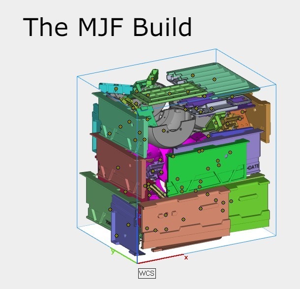
Component orientation is how a part sits in the build volume: flat, upright, tilted, or angled. In Multi Jet Fusion, that one choice ripples into surface quality, dimensional accuracy, print time, and how many parts fit around it. 3D nesting is the next layer up: arranging many parts throughout the build in three dimensions, not just across the print bed. Because MJF is a powder bed process, parts float at different heights and angles, so nesting is about filling the whole box.
Here is what most general 3D printing advice gets wrong for MJF. In FDM and SLA, build orientation strongly changes part strength because layers bond weakly along the Z axis, which makes those parts anisotropic. MJF is different. HP PA12 parts come out near-isotropic, so the strength gap between vertical and horizontal builds is small. Breaking stress is similar on all three axes; the real difference is ductility, where elongation at break drops by roughly half along Z. So orientation here is less about optimal strength and more about surface finish, accuracy, and cost.
Why MJF needs no support structures
If you came from FDM or SLA, your instinct is to orient a part to reduce support material and hide support marks. In those processes, poor orientation means overhangs sag and support volume climbs, and you lose post-processing time scraping support marks off the finished part. This additive manufacturing headache disappears in MJF: the unfused powder around each part is the support, so the process is self-supporting and needs no support structures.
That reshapes nesting. With no support structures to plan around and no support material to budget, you nest parts freely in 3D and orient each one purely for finish and accuracy. It is why HP MJF 3D printing packs so densely and costs so little per part at volume. Choosing a process? Our MJF vs FDM comparison shows where each one fits.
How orientation affects surface finish
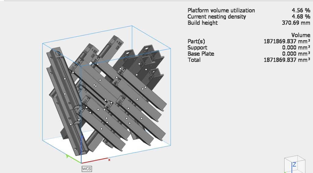
Surface quality is where orientation earns its keep. Every part is built from powder layers 80 microns thick (0.08 mm). On a face that runs nearly flat and points up, those layers show as fine stepping, like contour lines on a map. Tilt the face and the steps blend away. HP's guidance is to keep angles above about 20 degrees between large flat areas and the XY plane on upward-facing surfaces; downward faces are largely free of stepping.
For color parts, orient around the faces you plan to dye or smooth, then let post-processing finish the job. Our MJF post-processing guide shows how far a finish can go after the build.
How orientation affects dimensional accuracy
Accuracy in MJF is not equal in every direction, and orientation quietly decides whether a part passes inspection. HP's PA12 data on the Jet Fusion 5200 series shows XY holding tighter than Z: roughly ±0.25 mm in XY versus ±0.42 to 0.60 mm in Z for features up to 30 mm, at a Cpk of 1.33. The cause is thermal, since heat builds and releases unevenly through the stack, so deformation is harder to control along Z.
The rule is simple: put critical dimensions, mating faces, and hole patterns flat in the XY plane, and accept looser tolerance on Z features. For anything that must be dead-true, print near-net and finish by machining. Warping is the exception in MJF, but large flat plates and long spans move most, so orientation and nesting matter most there. Our MJF design guidelines go deeper on feature-level rules.
Nesting for cost and lead time
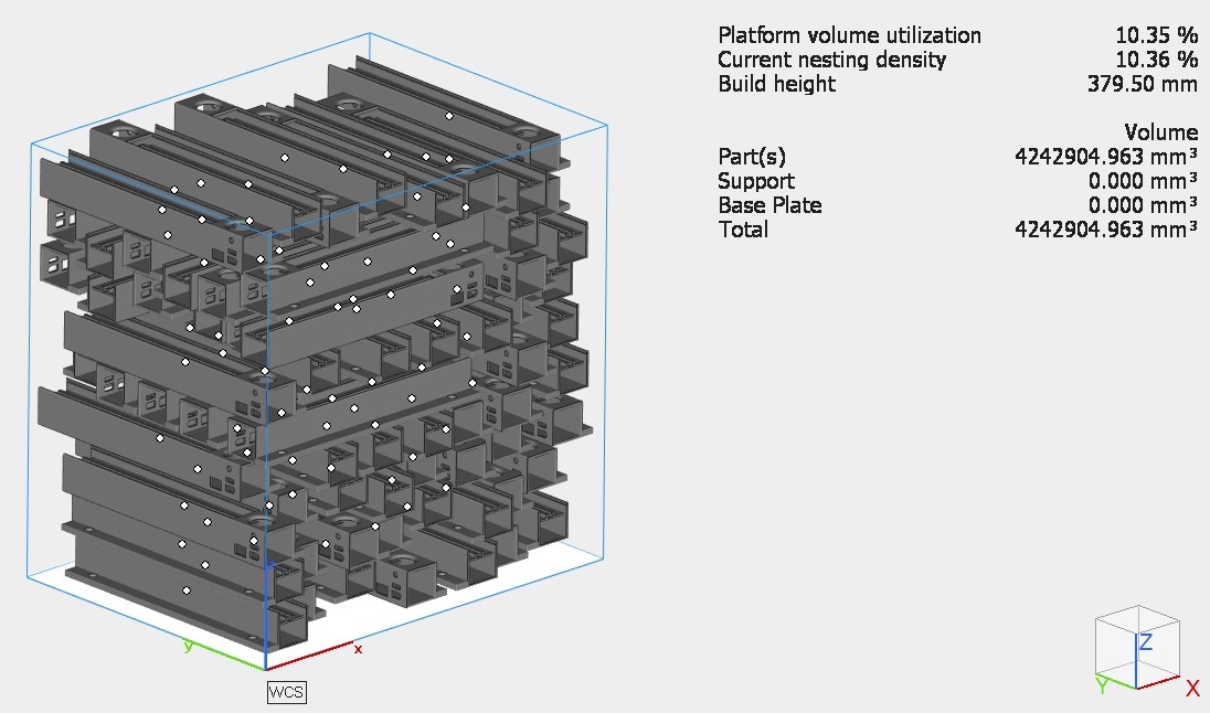
MJF economics are built on the box. Fill the build with hundreds of parts and the fixed cost of the run spreads thin, so cost per part falls. That is the point of 3D nesting: maximize material use, minimize wasted space, and pull more finished parts from one cycle. Printing multiple parts this way also shortens lead times. A few numbers to anchor the plan:
- Packing density: HP suggests around 8 to 10 percent as a balance of throughput and quality; dense production builds run higher. More density lowers cost but adds heat.
- Part spacing: Keep about 2 to 3 mm between parts so powder drains and the build stays stable. This is tighter than older rules and lets you nest more parts.
- Z height wins: Print time and cooling scale with build height, so a short stack is the fast path. Printing a 120 mm part vertically versus 70 mm laid flat cuts the number of layers by about 42 percent, and roughly that much print time.
Orientation also lets you trade speed for quality: faster build and cooling modes shorten the cycle but give up some surface finish and mechanical consistency.
Practical nesting and orientation tips
- Use proper nesting software. HP SmartStream Build Manager or Materialise Magics let you rotate parts, track packing density and build height, and set a cooling profile.
- Angle flat surfaces and face cosmetic detail downward. Tilt near-horizontal faces above 20 degrees to limit stepping and protect small part features.
- Label the intended orientation in CAD. So the operator does not rotate away a fit or finish, then pilot new geometries before locking orientation for repeat builds.
How Amuse 3D handles this for you
At Amuse 3D, orientation and nesting are set before a single part reaches the powder bed. We run one of India's largest HP MJF 5620 fleets, and every file is reviewed for the right orientation given its finish, accuracy, and cost priorities, whether it is a one-off prototype or a production batch. Our facility is ISO 9001:2015 and IATF 16949:2016 certified, and parts leave with your choice of industrial finishes, backed by our nylon PA12 material range.
Final takeaways
In MJF, orientation and 3D nesting decide cost per part, surface finish, and dimensional accuracy far more than raw strength, because the process is near-isotropic and self-supporting. Keep critical features in XY, angle or invert cosmetic faces, pack the build near 8 to 10 percent density with 2 to 3 mm spacing, and orient for a short Z height when speed matters.
Want your parts nested and oriented by an engineering team instead of by guesswork? Get an instant quote or upload your 3D CAD and we will handle the build strategy.
Frequently Asked Questions
1. Does part orientation affect strength in MJF?
Far less than in FDM or SLA. HP PA12 parts are near-isotropic, so breaking strength is similar in every direction; the main change is ductility, with elongation at break dropping about half along Z. You orient for finish, accuracy, and cost, not for strength.
2. Why don't MJF parts need support structures?
The unfused powder around each part supports it during the build, so MJF is self-supporting. There is no support material and no support marks to clean up, which is why parts can nest freely in 3D.
3. What is a good packing density for an MJF build?
HP suggests around 8 to 10 percent as a balance of throughput and quality, and dense production builds run higher. Higher density lowers cost per part but adds heat, so it is a trade-off, not a number to max out blindly.
4. Which surfaces come out smoothest in MJF?
Downward-facing and steeply angled ones. Flat, upward-facing faces show the most stepping from the 80-micron layers, so orient cosmetic faces downward or above roughly 20 degrees to the print

.png)