Rapid Prototype Manufacturing: A CAD-to-Part Workflow That Holds Up in Real Testing
Every physical product goes through the same tension: ship fast or ship right. Rapid prototype manufacturing lets engineering teams try to do both. It takes a 3D CAD file and turns it into a tested, functional part in days, so the design gets pressure-tested before tooling spend gets locked in.
That speed only pays off when the prototype behaves like the final product. A part that looks correct but folds under load tells you nothing useful. This guide covers how rapid prototype manufacturing actually moves a CAD model to a working part, which manufacturing process fits which use case, and how to decide when a prototype is ready for production. It also walks through the common rapid prototyping process families, how each fits into design and manufacturing today, and the real advantages of rapid prototyping over traditional manufacturing methods.
What Rapid Prototype Manufacturing Actually Is
Rapid prototype manufacturing is the process of converting a 3D CAD file into a physical part using additive manufacturing, CNC machining, or injection molding. The point is speed of iteration, not final aesthetics. It sits at the crossover of digital manufacturing and shop-floor build, letting product designers create prototypes in the same week they finish the model.
Where traditional manufacturing needs weeks of tool cutting for a first shot, rapid prototyping manufacturing runs straight from the digital file. That opens the door to multiple prototype rounds inside a single sprint. Modern additive manufacturing technologies and 3D printing technologies now cover everything from a rough concept model to a low-volume production part in the actual production material.
Engineers use these parts for:
- Dimensional and tolerance checks
- Assembly fit against mating components
- Mechanical strength and functional testing
- User feedback and ergonomic review
- Design validation before tooling spend
The Wohlers Report pegged the additive manufacturing industry at $20 billion in 2023, with rapid prototype development and low-volume production driving most of the growth. The same report calls prototyping and production the two largest end uses of the technology today.
What Makes a Prototype Truly Functional
A prototype is functional when it performs the way the final product will, not just when it looks the part. That means it survives the load, the temperature, and the assembly it will meet in real use.
Structural loads, target operating temperatures, and clean mating with neighboring components all matter. Fail the mechanical test phase early and the part has not earned its way through engineering sign-off.
Material choice matters as much as the manufacturing method. A visual resin part from SLA tells you nothing useful about a load-bearing bracket. Nylon PA12 through HP MJF or aluminum through CNC will.
From CAD to Part: How the Workflow Runs
The physical work follows a fairly consistent path from digital model to physical part.
CAD preparation-
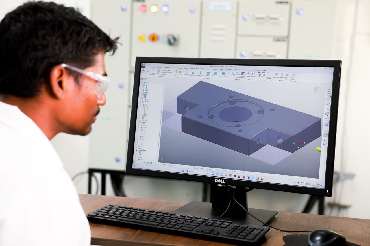
The 3D CAD file is finalized, checked for closed geometry, and exported as STL, STEP, or 3MF. Wall thickness, overhangs, and clearances get a first pass here.
DFM review-
Once you upload the 3D CAD file, an automated design-for-manufacturing check flags anything that will fail downstream. Amuse's platform checks against MJF guidelines for minimum wall thickness of 0.5mm and a mating clearance of at least 0.4mm, straight from HP's official MJF Handbook.
Toolpath and build file generation-
For CNC, the CAD model becomes toolpaths for a mill. For any layered additive manufacturing process, the file is sliced layer by layer. Either way, the digital model turns machine-ready. This step aligns with the seven process families defined by ISO/ASTM 52900, the international standard for additive manufacturing terminology.
Actual manufacturing-
Material goes in, layers stack up or chips come off, and a physical prototype comes out matching the original CAD design within the process's dimensional tolerance. Every actual manufacturing process, whether powder bed, filament, or milled metal, ends with the same test: does the physical part match the file. This is where the 3D printing process (or its subtractive equivalent) turns the file into a 3D printed part you can hold.
Post-processing-
Support removal, sandblasting, dyeing, or vapor polishing, depending on the surface finish spec. Skip this and the part often falls short of the drawing.
3D Printing, MJF, or CNC Machining: Picking the Right Process
Different types of rapid prototyping produce very different mechanical properties out of the same CAD file. Cost, lead time, and whether the part survives testing all shift with the process pick. There are four common methods for rapid prototyping in industrial use today, plus sheet metal fabrication for flat brackets and enclosures.
Multi Jet Fusion is the workhorse for durable, near-isotropic nylon parts. CNC machining wins when you need real metal, tight tolerance, and a clean finish. Selective laser sintering (also written SLS or SL) sits close to MJF for engineering-grade thermoplastic. SLA is the pick when the prototype is about visual approval, not load. Each of these manufacturing techniques carries different manufacturing technologies underneath, and the pick shapes cost, strength, and finish.
Material Choice Changes Everything
The right manufacturing process with the wrong material still fails design validation. Nylon PA12 through MJF gets you tough, impact-resistant prototype parts. Aluminum 6061 through CNC gets you real stiffness and a metal finish you can anodize.
For anything moving toward end-use, the choice narrows fast. Selective laser sintering or MJF for thermoplastic housings. CNC for a plastic or metal bracket that has to hold torque. Rapid injection molding when you need 50 to 500 parts in the actual production polymer, whether that is metal and plastic combined or a single-material run.
5 Mistakes That Slow Down Rapid Prototype Development
Even experienced teams trip on the same things.
1. Ignoring DFM rules.
Walls under 0.3mm on MJF bend or crack. Overhangs without support on CNC add hours of setup.
2. Wrong tolerances.
Asking for clearance tighter than ±0.2mm on MJF usually adds cost with no benefit.
3. Wrong process for the test.
Visual resin parts fail load testing. High-precision CNC on an appearance model wastes budget.
4. Low-resolution mesh files.
Coarse STL exports give you faceted circles. Export at high resolution.
5. Skipping post-processing.
Miss a thermal or sandblasting step and the part reads soft, dull, or dimensionally off.
How Rapid Prototype Manufacturing Speeds Design Iteration
The real value of rapid prototype manufacturing is not the first part. It is running multiple iterations in a week and treating each one as fresh data, not a failure. Rapid prototyping allows the team to fold real user feedback into the next version instead of waiting a full quarter for it.
A tweaked CAD model on Monday can be a functional part by Wednesday. That kind of rapid turnaround lets design and engineering teams test three variants of a snap fit or two wall thicknesses side by side, instead of betting the sprint on one guess. The result is prototypes and functional parts that clear real testing before anyone commits to tooling. Rapid prototyping helps compress the product development cycle from months to weeks and shortens the whole development process from concept to sign-off. Prototyping helps at every stage of the product development process, not just the first sketch.
When Your Prototype Is Ready for Production
A prototype clears the last gate when it has passed functional testing under real conditions, matched the CAD model within tolerance, and mated cleanly with neighbors across multiple iterations.
Once the geometry is locked, the next step is production drawings, quality control specs, and a manufacturing method that scales. That might be bridge tooling, rapid tooling with aluminum molds for short runs, or steel injection molding for real volume. Prototype to production is a decision about lead time, cost per part, and volume, not just capability. Rapid manufacturing sits in between, letting a business ship real parts while the tooling story catches up.
Conclusion
Rapid prototype manufacturing is more than pushing a 3D CAD file to a printer. It is design validation, material selection, functional testing, and a manufacturing method that matches the part's real job. Get those four right and the prototype earns the trust of the engineers signing off on it. This is the direction the future of manufacturing is heading, with prototyping technology and rapid prototyping technology closing the gap between digital design and shipped parts.
Amuse 3D runs rapid prototype production through HP MJF, CNC machining, and molding services, with engineers reviewing every CAD file before it hits the shop floor. Talk to us for a rapid prototyping service or full production services quote, or start with an instant quote on your next rapid prototype development project.
Frequently Asked Questions
1. How fast is rapid prototype manufacturing?
Lead times depend on process and part size. HP MJF parts typically ship in 3 to 5 working days inside India and 4 to 7 days worldwide. CNC machining runs similarly, sometimes longer for complex geometries or hardened metals.
2. Can rapid prototyping produce end-use parts?
Yes, for the right applications. Selective laser sintering, MJF, and rapid injection molding all produce end-use parts, from drone housings to medical fixtures. The pick depends on load, environment, and volume.
3. Is 3D printing or CNC machining better for rapid prototypes?
Neither wins outright. 3D printing is better for complex geometries, internal channels, and quick design changes. CNC machining is better for tight tolerance parts, metals, and surface-critical components. Many projects use both.

.png)