Mastering Orientation & 3D Nesting: Your Ultimate Guide to Unlocking High-Quality, Cost-Effective HP MJF 3D Printing Parts.
Achieving seamless and accurate 3D prints can be a challenging task, especially when it comes to small parts or a collection of 3D parts. That’s where 3D nesting comes into play. These techniques optimize the placement and orientation of parts in a print, resulting in efficient material usage and improved print quality. In this article, we’ll discuss the things you need to know about 3D nesting to help you achieve perfectly layered 3D prints.
What is component orientation in MJF 3D printing?
Component orientation refers to how parts are positioned during the printing process. It is an important consideration in Multi-Jet Fusion 3D printing, as it can greatly affect the strength of the final product. When parts are oriented correctly, they are less likely to warp or distort during the printing process, and the overall quality of the finished product is improved.
Importance of part orientation
As we discussed earlier, part orientation (component orientation) in 3D printing refers to the positioning of a model on the print bed. It helps in determining the quality of the final 3D-printed part. Proper part orientation ensures that the structural integrity and strength of the model are optimized while minimizing the number of support structures needed during printing.
Inadequate part orientation can lead to weak and brittle parts, surface defects, and other printing issues. This can result in wasted material, time, and money. A poorly oriented part can also lead to difficulty in removing support structures and a rough surface finish.
By carefully considering the part's geometry and selecting the right orientation, it is possible to achieve high-quality, strong, and accurate parts with minimum support material. So it is an essential aspect of 3D printing that should not be overlooked as it can significantly impact the final result.
What is 3D Nesting?
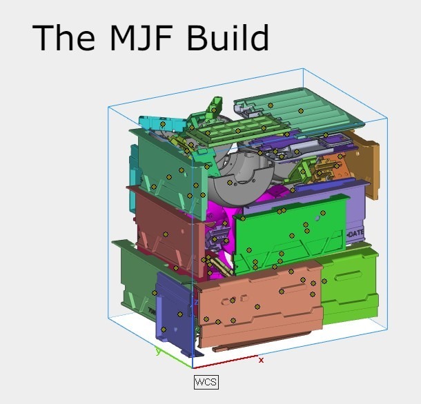
3D nesting is the process of arranging 3D models in a print to optimize the use of material and minimize print time. It involves placing multiple models within the build volume of a 3D printer in a way that minimizes empty spaces and reduces the need for support structures.
Example: Printing multiple parts - When printing multiple parts simultaneously, 3D nesting can be used to optimize the placement of parts within the build volume, while 3D building can be used to optimize the orientation of each part. This results in improved print quality and increased efficiency.
More parts in the build translate into low cost of manufacturing
Importance of 3D nesting
When it comes to 3D printing technologies like Multi Jet Fusion (MJF) the size of the "build" can decrease the cost of the prints. By filling each build with hundreds of items, the cost per part decreases, making the entire print run more valuable.
That's why techniques like 3D nesting are so important. They allow you to optimize the placement and orientation of each part within the build, maximizing the number of items you can fit and minimizing the amount of wasted space.
How effective is 3D nesting when time is a major factor?
In addition to cost savings, filling each build with as many parts as possible can also help reduce lead times. Rather than waiting for multiple smaller builds to finish printing, you can print everything in a single run, reducing the overall time required to produce the desired number of parts. This is especially useful when working on large-scale production runs or when time is of the essence.
But it's not just about packing as many parts as possible into each build. Properly orienting each part can also have a major impact on print quality. By using techniques like this, you can ensure that each part is printed quickly, reducing the need for support structures and improving the overall strength and durability of the 3D part. By maximizing the number of parts you can fit into each build and ensuring that each part is printed in the most optimal way possible, you can achieve perfectly layered 3D prints that are strong, durable, and cost-effective.
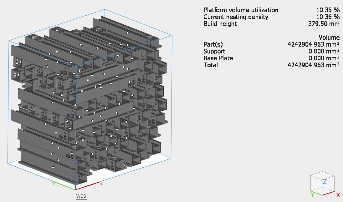
When TIME & COST are important over surface QUALITY
From the picture below, you can observe that the parts are densely packed, and the packing density is close to 10%, which is indicative of a potentially profitable business. If your primary focus is on time and cost reduction, there are alternative approaches to consider. Instead of the balanced mode and natural cooling, which are commonly used methods, you can explore the fast mode and rapid cooling options. By opting for the fast mode, you can potentially accelerate production by 30% to 40%.
At Amuse3D we deploy advanced post-processing techniques to get parts with extremely high finish. In this way, you still have quality parts at affordable cost.

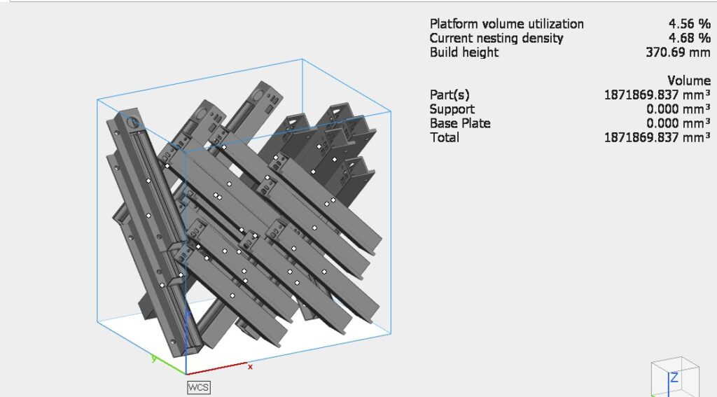
QUALITY is the priority
"From the picture below, you can observe that the parts are oriented at a 45-degree angle, and the packing density is approximately 5% lower compared to the previous build. With this orientation, we would need to run the machine twice to achieve the same output quantity. This option should be considered when stringent surface and dimensional accuracy is required. Instead of the balanced mode mentioned earlier, you can enhance the mechanical properties by printing this build in the mechanical mode. However, it's important to note that this may result in a slight trade-off between time and surface finish compared to the balanced mode printing."

Tips for 3D nesting practice
- Choose the Right Software: Consider software options like Netfabb, Materialise Magics or other relevant 3D nesting software.
- Guidelines for perfect 3D nesting preparation
When working with powder-based 3D printers like Multi Jet Fusion printers, it's important to follow these guidelines to get the best results:
- Avoid flat surfaces and angle horizontal surfaces 20 degrees or higher
- Keep a minimum spacing of 5mm between parts
- Parts with fine details should be faced downwards
Following these guidelines will help ensure that your 3D prints come out correctly and with a high level of quality. By avoiding flat surfaces and angling horizontal surfaces, you can prevent unwanted defects and ensure that your parts are printed as intended. Additionally, spacing parts apart and facing fine details downwards will help prevent collisions and maintain detail integrity. Keep these guidelines in mind when working with powder-based 3D printers for optimal results.
Tips for proper MJF component orientation
Here are a few tips which you can utilize to make perfect 3D-printed objects by properly aligning the components/parts.
- Consider the shape of the part: The shape of the part being printed should be taken into consideration when determining its orientation. Parts with a large surface area or those with overhangs are more likely to warp during the printing process, so they should be oriented in a way that minimizes these risks.
- Use support structures: Support structures can be used to provide additional stability to parts during the printing process. They are especially useful for parts with unnatural geometries or those with overhangs.
- Position parts to minimize the number of layers: The number of layers required to print a part can affect its strength and quality. Positioning parts properly helps in minimizing the number of layers required to improve the final product.
- Consider the direction of the print head: The direction of the print head can affect the rigidity of the final product. components should be oriented in a way that allows the print head to move smoothly and efficiently.
- Test and adjust: Testing and adjusting the orientation of parts during the printing process can help to optimize the final product. By making small adjustments and retesting, you can find the optimal orientation for each part.
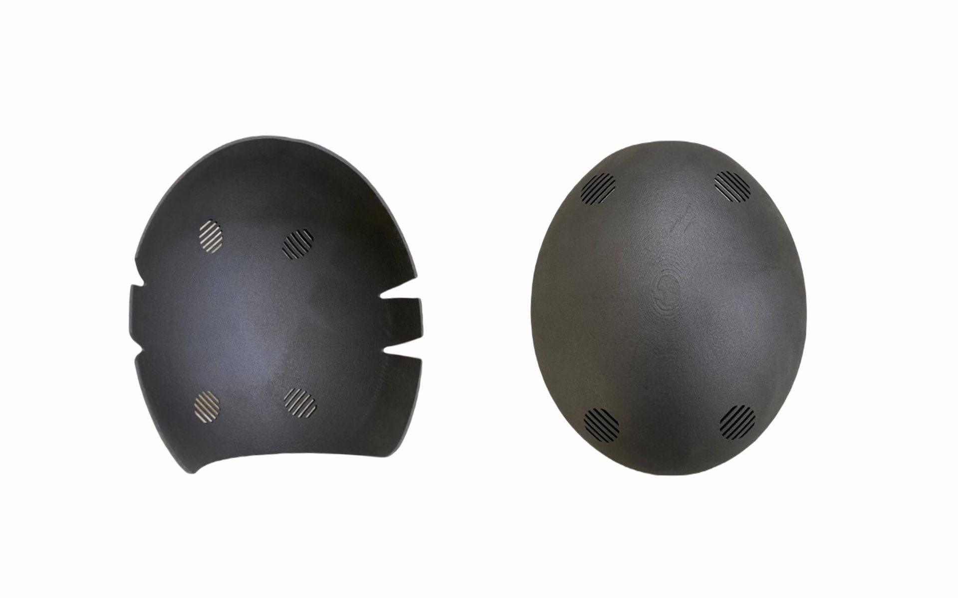
MJF component orientation: Surface facing z- and z+
Downwards facing surfaces (Z-):
Surfaces with an angle of less than 30° to the XY plate that is facing downwards receive adequate support to create themselves correctly. The layer-by-layer process results in a very uniform finish that is practically free of any signs of layer scaling. This makes downwards-facing surfaces ideal for achieving a high-quality, smooth finish.
Upwards facing surfaces (Z+):
On the other hand, upwards-facing surfaces (Z+) with angles of less than 30° to the XY plate will have more marked scaling from the individual layers. This is because the material or the object’s heat gets dissipated in the central area, which leads to a decrease in volume and contracting. This may cause surfaces that are facing upwards to be concave.

Printed parts in MJF upward (left) and downward (right) print
Final Thoughts
In conclusion, The orientation of the component affects the accuracy, surface finish, and strength of the outcome.
By following the tips on how to orient components in MJF for the best results, you can achieve high-quality prints with optimal strength and accuracy. Properly orienting components in MJF ensures that the layers are well-supported and that the 3D part is printed with minimal distortion. Following these guidelines will help ensure that your 3D prints come out correctly and with a high level of quality. By avoiding flat surfaces and angling horizontal surfaces, you can prevent unwanted defects and ensure that your parts are printed as intended. Additionally, spacing parts apart and facing fine details downwards will help prevent collisions and maintain detail integrity. Keep these guidelines in mind when working with powder-based 3D printers for optimal results.
We hope this article has provided you with valuable insights into MJF component orientation in 3D printing. If you need high-quality, industry-level 3D-printed parts, be sure to check out Amuse 3D.


.png)